IS-456 has laid down the acceptance criteria of quality concrete. In all the cases, the 28-days compressive strength shall alone be the criterion for acceptance or rejection of the concrete. 7 days compressive strength of concrete can be carried out in order to get a relatively quicker idea regarding the quality of concrete.
PROCEDURE OF TEST CUBE PREPARATION
EQUIPMENT
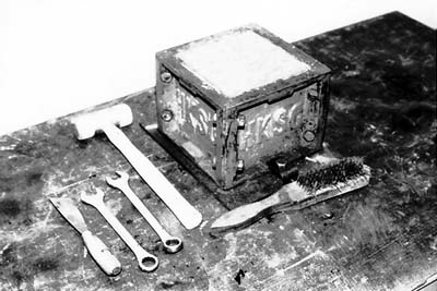
The following equipments are needed for the preparation of concrete cubes.
Sample tray;
Mould for making test cube;
Spanner;
Scoop;
Steel float or trowel;
Compacting bar;
Cleaning rags;
A bucket or barrow for transporting the samples;
Curing tank
Permanent Marker.
NO OF CUBES
6 no of Cubes of 150 x 150 x 150 mm size shall be cast, 3 for 7-days testing and 3 for 28-days testing. A sample consists of 3 cube specimens and their average compressive strength represents the test result of that sample. The individual variation of a set of 3 cubes should not be more than ± 15% of the average. If more, the test result of the sample is invalid.
SAMPLE OF CONCRETE
Sample of concrete for test specimen shall be taken at the mixer or in the case of ready mixed concrete from the transportation vehicle at the time of discharge. Such samples shall be obtained by repeatedly passing a scoop or pail through the discharge stream of the concrete. The samples thus obtained shall be mixed on a non-absorbent base with shovel until it is uniform in appearance.
Number of samples to be taken depends on the quantity of concrete. As per IS-456, the following table shall be followed during sampling.
Quantity of concrete in the work (m3)
Number of samples
1-5
1
6-15
2
16-30
3
31-50
4
51 and above
4 plus one additional sample for each additional 50 m3 or part thereof.
Note:- Frequency of sampling may be agreed upon internally by supplier and purchaser.
CASTING OF CUBES
The cube mould plates should be removed, properly cleaned assembled and all the bolts should be fully tight. A thin layer of oil then shall be applied on all the faces of the mould. It is important that cube side faces must be parallel.
After taking concrete samples and mixing them, the cubes shall be cast as soon as possible as described below.
CASTING & COMPACTION BY HAND
The concrete sample shall be filled into the cube moulds in 3 layers, each layer approximately 5 cm deep. In placing each scoopful of concrete, the scoop shall be moved around the top edge of the mould as the concrete slides from it, in order to ensure a symmetrical distribution of the concrete within the mould. Each layer shall be compacted either by hand or by the vibration. Each layer of the concrete filled in the mould shall be compacted by not less than 35 strokes by tamping bar. The strokes shall be penetrating into the underlying layer and the bottom layer shall be rodded throughout its depth. Where voids are left by the tamping bar the sides of the mould shall be tapped to close the voids.
CURING
The casted cubes shall be stored under shed at a place free from the vibration at a temperature 220C to 330C for 24 hours covered with wet straw or gunny sacking.
MARKING
Immediately after initial curing of the cubes they should be marked clearly. This can be done by writing the details of the cube in ink on a small piece of paper and placing on top of the concrete until it is demoulded.
The cube shall be removed from the moulds at the end of 24 hours and immersed in clean water at a temperature 240C to 300C till the 7 or 28-days age of testing. The cubes shall be tested in the saturated and surface dry condition.
For the true representation of actual strength of concrete in the structure, extra cubes shall be cast, stored and curded as per the identical conditions of that structure, and tested at required age.
NOTE: WHEN MOULDS ARE NOT IN USE, APPLY A THIN LAYER OF OIL OVER THE INSIDE SURFACE OF THE MOULD AND KEEP IT IN A SAFE PLACE.
IS-10262-2009-CONCRETE MIX DESIGN – INDIAN STANDARD METHOD
The following points should be remembered before proportioning a concrete mix a per IS-10262-2009.
This method of concrete mix proportioning is applicable only for ordinary and standard concrete grades.
The air content in concrete is considered as nil.
The proportioning is carried out to achieve specified characteristic compressive strength at specified age, workability of fresh concrete and durability requirements.
Concrete Mix Design
This method of concrete mix design consist of following 11 steps
Design specification
Testing of materials
Calculating target strength for mix proportioning
Selecting water/cement ratio
Calculating water content
Calculating cement content
Finding out volume proportions for Coarse aggregate & fine aggregate
11. Repeating step 9 & 10 until all requirements is fulfilled.
Let us discuss all of the above steps in detail
STEP-1. DESIGN SPECIFICATIONS
This is the step where we gather all the required information for designing a concrete mix from the client. The data required for mix proportioning is as follows.
Grade designation (whether M10, M15, M20 etc)
Type of cement to be used
Maximum nominal size of aggregates
Minimum & maximum cement content
Maximum water-cement ratio
Workability
Exposure conditions (As per IS-456-Table-4)
Maximum temperature of concrete at the time of placing
Method of transporting & placing
Early age strength requirement (if any)
Type of aggregate (angular, sub angular, rounded etc)
Type of admixture to be used (if any)
STEP-2. TESTING OF MATERIALS
The table given below shows the list of most necessary tests to be done on cement, coarse aggregate, fine aggregate and admixture. After doing the test, store the test data for further calculation.
Concrete Ingredients
Tests to be done
Cement
Specific gravity
—
—
—
Coarse aggregate
Specific gravity
Water absorption
Free surface moisture
Sieve analysis
Fine aggregate
Specific gravity
Water absorption
Free surface moisture
Sieve analysis
Admixture
(if any)
Specific gravity
—
—
—
STEP-3. TARGET STRENGTH CALCULATION
Calculate the target compressive strength of concrete using the formula given below.
fck’ = fck + 1.65s
Where,
fck’ = Target compressive strength at 28 days in N/mm2.
fck = Characteristic compressive strength at 28 days in N/mm2. (same as grade of concrete, see table below)
s = Standard deviation
The value of standard deviation, given in the table below, can be taken for initial calculation.
Sl.No
Grade of Concrete
Characteristic compressive strength (N/mm2)
Assumed standard deviation (N/mm2)
1.
M10
10
3.5
2.
M15
15
3.
M20
20
4.0
4.
M25
25
5.
M30
30
6.0
6.
M35
35
7.
M40
40
8.
M45
45
9.
M50
50
10.
M55
55
STEP-4. SELECTION OF WATER-CEMENT RATIO
For preliminary calculation, water cement ratio as given is IS-456-Table 5 (also given below) for different environmental exposure condition, may be used.
Note: Use Table-1 for finding out water-cement ratio of Plain Concrete and use Table-2 for finding out water-cement ratio of Reinforced Concrete.
Table -1
Sl.No.
Environmental Exposure Condition
Plain Concrete
Minimum Cement Content (kg/m3)
Maximum Free Water-Cement Ratio
Minimum Grade of Concrete
1
Mild
220
0.60
—
2
Moderate
240
0.60
M15
3
Severe
250
0.50
M20
4
Very Severe
260
0.45
M20
5
Extreme
280
0.40
M25
Table -2
Sl.No.
Environmental Exposure Condition
Reinforced Concrete
Minimum Cement Content (kg/m3)
Maximum Free Water-Cement Ratio
Minimum Grade of Concrete
1
Mild
300
0.55
M20
2
Moderate
300
0.50
M25
3
Severe
320
0.45
M30
4
Very Severe
340
0.45
M35
5
Extreme
360
Refer the table given below (As per IS-456) to choose right type of environment depending upon different exposure conditions to concrete.
Sl.No
Environment
Exposure condition
1
Mild
Concrete surfaces protected against weather or aggressive conditions, except those situated in coastal areas.
2
Moderate
Concrete surfaces sheltered from severe rain or freezing whilst wetConcrete exposed to condensation and rain
Concrete continuously under water
Concrete in contact or buried under non aggressive soil/ground water
Concrete surfaces sheltered from saturated salt air in coastal area
3
Severe
Concrete surfaces exposed to severe rain, alternate wetting and drying or occasional freezing whilst wet or severe condensationConcrete completely immersed in sea water
Concrete exposed to coastal environment
4
Very severe
Concrete surfaces exposed to sea water spray, corrosive fumes or severe freezing condition whilst wetConcrete in contact with or buried under aggressive sub-soil/ground water
5
Extreme
Surface members in tidal zoneMembers in direct contact with liquid/solid aggressive chemicals
STEP-5. SELECTION OF WATER CONTENT
Selection of water content depends upon a number of factors such as
Aggregate size, shape & texture
Workability
Water cement ratio
Type of cement and its amount
Type of admixture and environmental conditions.
Factors that can reduce water demand are as follows
Using increased aggregate size
Reducing water cement ratio
Reducing the slump requirement
Using rounded aggregate
Using water reducing admixture
Factors that can increase water demand are as follows
Increased temp. at site
Increased cement content
Increased slump
Increased water cement ratio
Increased aggregate angularity
Decrease in proportion of the coarse aggregate to fine aggregate
The quantity of maximum mixing water per unit volume of concrete may be selected from the table given below.
Maximum water content per cubic meter of concrete for nominal maximum size of aggregate
Sl.No.
Nominal maximum size of aggregate
Maximum water content
1
10
208
2
20
186
3
40
165
The values given in the table shown above is applicable only for angular coarse aggregate and for a slump value in between 25 to 50mm.
Do the following adjustments if the material used differs from the specified condition.
Type of material/condition
Adjustment required
For sub angular aggregate
Reduce the selected value by 10kg
For gravel with crushed stone
Reduce the selected value by 20kg
For rounded gravel
Reduce the selected value by 25kg
For every addition of 25mm slump
Increase the selected value by 3%
If using plasticizer
Decrease the selected value by 5-10%
If using super plasticizer
Decrease the selected value by 20-30%
Note: Aggregates should be used in saturated surface dry condition. While computing the requirement of mixing water, allowance shall be made for the free surface moisture contributed by the fine and coarse aggregates. On the other hand, if the aggregate are completely dry, the amount of mixing water should be increased by an amount equal to moisture likely to be absorbed by the aggregate
STEP-6. CALCULATING CEMENTIOUS MATERIAL CONTENT
From the water cement ratio and the quantity of water per unit volume of cement, calculate the amount of cementious material. After calculating the quantity of cementious material, compare it with the values given in the table shown in Step-4. The greater of the two values is then adopted.
If any mineral admixture (such as fly ash) is to be used, then decide the percentage of mineral admixture to be used based on project requirement and quality of material.
STEP-7. FINDING OUT VOLUME PROPORTIONS FOR COARSE AGGREGATE & FINE AGGREGATE
Volume of coarse aggregate corresponding to unit volume of total aggregate for different zones of fine aggregate is given in the following table.
Sl.No.
Nominal
Maximum
Size of
Aggregate
(mm)
Volume of coarse aggregate per unit volume of total aggregate for different zones of fine aggregate
Zone IV
Zone III
Zone II
Zone I
1
10
0.50
0.48
0.46
0.44
2
20
0.66
0.64
0.62
0.60
3
40
0.75
0.73
0.71
0.69
The values given in the table shown above is applicable only for a water-cement ratio of 0.5 and based on aggregates in saturated surface dry condition.
If water-cement ratio other than 0.5 is to be used then apply correction using the rule given below.
Rule: For every increase or decrease by 0.05 in water-cement ratio, the above values will bedecreased or increased by 0.01, respectively.
If the placement of concrete is done by a pump or where is required to be worked around congested reinforcing steel, it may be desirable to reduce the estimated coarse aggregate content determined as above, upto 10 percent.
After calculating volume of coarse aggregate, subtract it from 1, to find out the volume of fine aggregate.
STEP-8. MIX CALCULATIONS
The mix calculations per unit volume of concrete shall be done as follows.
a
Volume of concrete=
1m3
b
Volume of cement=
(Mass of cement/specific gravity of cement)*(1/1000)
c
Volume of water=
(Mass of water/specific gravity of water)*(1/1000)
d
Volume of admixture=
(Mass of admixture/specific gravity of admixture)*(1/1000)
e
Volume of total aggregate (C.A+F.A)=
[a-(b+c+d)]
f
Mass of coarse aggregate=
e*Volume of coarse aggregate*specific gravity of coarse aggregate*1000
g
Mass of fine aggregate=
e*Volume of fine aggregate*specific gravity of fine aggregate*1000
STEP-9. TRIAL MIX
Conduct a trial mix as per the amount of material calculated above.
STEP-10. MEASUREMENT OF WORKABILITY (BY SLUMP CONE METHOD)
The workability of the trial mix no.1 shall be measured. The mix shall be carefully observed for freedom from segregation and bleeding and its finishing properties.
STEP-11. REPEATING TRIAL MIXES
If the measured workability of trial mix no.1 is different from stipulated value, the water and/or admixture content shall be adjusted suitably. With this adjustment, the mix proportion shall be recalculated keeping the free water-cement ratio at pre-selected value.
Trial-2 – increase water or admixture, keeping water-cement ratio constant
Trial-3 – Keep water content same as trial-2, but increase water-cement ratio by 10%.
Trial-4 – Keep water content same as trial-2, but decrease water-cement ratio by 10%
Trial mix no 2 to 4 normally provides sufficient information, including the relationship between compressive strength and water-cement ratio.
WORKABILITY TEST OF CONCRETE BY VEE-BEE CONSISTOMETER METHOD (IS-1199-1956)
OBJECTIVE
To determine the workability of freshly mixed concrete by using of Vee – Bee consistometer apparatus.
SCOPE AND SIGNIFICANCE
The workability of fresh concrete is a composite property, which includes the diverse requirements of stability, mobility, compactability, placeability and finishability. There are different methods for measuring the workability. Each of them measures only a particular aspect of it and there is really no unique test, which measures workability of concrete in its totality. This test gives an indication of the mobility and to some extent of the compactibility of freshly mixed concrete. The test measures the relative effort required to change a mass of concrete from one definite shape to another (i.e., from conical to cylindrical) by means of vibration. The amount of effort (called remoulding effort) is taken as the time in seconds, required to complete the change. The results of this test are of value when studying the mobility of the masses of concrete made with varying amounts of water, cement and with various types of grading of aggregate. The time required for complete remoulding in seconds is considered as a measure of workability and is expressed as the number of Vee-Bee seconds. The method is suitable for dry concrete. For concrete of slump in excess of 50mm, the remoulding is so quick that the time cannot measured.
Vee-Bee Consistometer
APPARATUS
Cylindrical container,
Vee-Bee apparatus (consisting of vibrating table, slump cone)
Standard tamping rod,
Stop watch and
trowels.
PROCEDURE
(1) Place the slump cone in the cylindrical container of the consistometer. Fill the cone in four layers, each approximately one quarter of the height of the cone. Tamp each layer with twenty-five strokes of the rounded end of the tamping rod. The strokes are distributed in a uniform manner over the cross-section of the cone and for the second and subsequent layers the tamping bar should penetrate into the underlying layer. After the top layer has been tamped, struck off level the concrete with a trowel making the cone exactly filled.
(2) Move the glass disc attached to the swivel arm and place it just on the top of the slump cone in the cylindrical container. Adjust the glass disc so as to touch the top of the concrete cone, and note the initial reading on the graduated rod.
(3) Remove the cone from the concrete immediately by raising it slowly and carefully in the vertical direction. Lower the transparent disc on the top of concrete. Note down the reading on the graduated rod.
(4) Determine the slump by taking the difference between the readings on the graduated rod recorded in the steps (2) and (3) above.
(5) Switch on the electrical vibrations and start the stopwatch. Allow the concrete to remould by spreading out in the cylindrical container. The vibrations are continued until the concrete is completely remoulded, i.e, the surfaces becomes horizontal and the whole concrete surface adheres uniformly to the transparent disc.
(6) Record the time required for complete remoulding seconds which measures the workability expressed as number of Vee-Bee seconds.
OBSERVATIONS AND CALCULATION
Initial reading on the graduated rod, a
Final reading on the graduated rod, b
Slump = (b) – (a), in cm
Time for complete remoulding, seconds
RESULTS
The consistency of the concrete is reported in seconds.
COMPRESSIVE STRENGTH TEST OF CONCRETE (IS:516-1959)
OBJECTIVE
The tests are required to determine the strength of concrete and therefore its suitability for the job.
REFERENCE STANDARDS
IS : 516-1959 – Methods of tests for strength of concrete.
EQUIPMENT & APPARATUS
Compression testing machine (2000 KN)
Curing tank/Accelerated curing tank
Balance (0-10 Kg)
Compressive Strength Test on Concrete
PROCEDURE
Representative samples of concrete shall be taken and used for casting cubes 15 cm x 15 cm x 15 cm or cylindrical specimens of 15 cm dia x 30 cm long.
The concrete shall be filled into the moulds in layers approximately 5 cm deep. It would be distributed evenly and compacted either by vibration or by hand tamping. After the top layer has been compacted, the surface of concrete shall be finished level with the top of the mould using a trowel; and covered with a glass plate to prevent evaporation.
The specimen shall be stored at site for 24+ ½ h under damp matting or sack. After that, the samples shall be stored in clean water at 27+20C; until the time of test. The ends of all cylindrical specimens that are not plane within 0.05 mm shall be capped.
Just prior to testing, the cylindrical specimen shall be capped with sulphur mixture comprising 3 parts sulphur to 1 part of inert filler such as fire clay.
Specimen shall be tested immediately on removal from water and while they are still in wet condition.
The bearing surface of the testing specimen shall be wiped clean and any loose material removed from the surface. In the case of cubes, the specimen shall be placed in the machine in such a manner that the load cube as cast, that is, not to the top and bottom.
Align the axis of the specimen with the steel platen, do not use any packing.
The load shall be applied slowly without shock and increased continuously at a rate of approximately 140 kg/sq.cm/min until the resistance of the specimen to the increased load breaks down and no greater load can be sustained. The maximum load applied to the specimen shall then be recorded and any unusual features noted at the time of failure brought out in the report.
CALCULATION
Compressive strength is calculate using the following formula
Compressive strength (kg/cm2) = Wf / Ap
Where
Wf = Maximum applied load just before load, (kg)
Ap = Plan area of cube mould, (mm2)
SAFETY & PRECAUTIONS
Use hand gloves, safety shoes & apron at the time of test.
After test switch off the machine.
Keep all the exposed metal parts greased.
Keep the guide rods firmly fixed to the base & top plate.
Equipment should be cleaned thoroughly before testing & after testing.
SPLITTING TENSILE STRENGTH TEST OF CONCRETE (IS-516)
DETERMINE SPLITTING TENSILE STRENGTH OF CYLINDRICAL CONCRETE SPECIMENS
OBJECTIVE:
This method covers the determination of the splitting tensile strength of cylindrical concrete specimens
REFERENCE:
IS: 516 – 1959, IS: 1199-1959, SP: 23-1982, IS: 10086-1982
THEORY:
Age at Test – Tests shall be made at recognized ages of the test specimens, the most usual being 7 and 28 days. Where it may be necessary to obtain the early strengths, tests may be made at the ages of 24 hours ± ½ hour and 72 hours ± 2 hours. The ages shall be calculated from the time of the addition of water to the dry ingredients.
Number of Specimens – At least three specimens, preferably from different batches, shall be made for testing at each selected age.
APPARATUS:
Testing Machine – The testing machine may be of any reliable type, of sufficient capacity for the tests and capable of applying the load at the rate specified in 5.5. The permissible error shall be not greater than ± 2 percent of the maximum load.
Cylinders –The cylindrical mould shall be of 150 mm diameter and 300 mm height conforming to IS: 10086-1982.
Weights and weighing device, Tools and containers for mi
xing, Tamper (square in cross section) etc.
PROCEDURE:
SAMPLING OF MATERIALS –
Samples of aggregates for each batch of concrete shall be of the desired grading and shall be in an air-dried condition. The cement samples, on arrival at the laboratory, shall be thoroughly mixed dry either by hand or in a suitable mixer in such a manner as to ensure the greatest possible blending and uniformity in the material.
PROPORTIONING –
The proportions of the materials, including water, in concrete mixes used for determining the suitability of the materials available, shall be similar in all respects to those to be employed in the work.
WEIGHING –
The quantities of cement, each size of aggregate, and water for each batch shall be determined by weight, to an accuracy of 0.1 percent of the total weight of the batch.
MIXING CONCRETE –
The concrete shall be mixed by hand, or preferably, in a laboratory batch mixer, in such a manner as to avoid loss of water or other materials. Each batch of concrete shall be of such a size as to leave about 10 percent excess after moulding the desired number of test specimens.
MOULD –
The cylindrical mould shall be of 150 mm diameter and 300 mm height conforming to IS: 10086-1982.
COMPACTING –
The test specimens shall be made as soon as practicable after mixing, and in such a way as to produce full compaction of the concrete with neither segregation nor excessive laitance.
CURING –
The test specimens shall be stored in a place, free from vibration, in moist air of at least 90 percent relative humidity and at a temperature of 27° ± 2°C for 24 hours ± ½ hour from the time of addition of water to the dry ingredients.
PLACING THE SPECIMEN IN THE TESTING MACHINE –
The bearing surfaces of the supporting and loading rollers shall be wiped clean, and any loose sand or other material removed from the surfaces of the specimen where they are to make contact with the rollers.
Two bearings strips of nominal (1/8 in i.e 3.175 mm) thick plywood, free of imperfections, approximately (25 mm) wide, and of length equal to or slightly longer than that of the specimen should be provided for each specimen.
The bearing strips are placed between the specimen and both upper and lower bearing blocks of the testing machine or between the specimen and the supplemental bars or plates.
Draw diametric lines an each end of the specimen using a suitable device that will ensure that they are in the same axial plane. Centre one of the plywood strips along the centre of the lower bearing block.
Place the specimen on the plywood strip and align so that the lines marked on the ends of the specimen are vertical and cantered over the plywood strip.
Place a second plywood strip lengthwise on the cylinder, cantered on the lines marked on the ends of the cylinder. Apply the load continuously and without shock, at a constant rate within, the range of 689 to 1380 kPa/min splitting tensile stress until failure of the specimen
Record the maximum applied load indicated by the testing machine at failure. Note the type of failure and appearance of fracture.
OBSERVATIONS:
Mix Proportion of Concrete
For 1 m3 of concrete
For one batch of concrete
Coarse aggregate (kg)
Fine aggregate (kg)
Cement (kg)
Water (kg)
S/A
w/c ratio
Admixture
Sl No
Age of Specimen
Identification Mark
Dia of Specimen (mm)
Depth (mm)
Maximum Load (N)
Tensile Strength (MPa)
Avg Tensile Strength (Mpa)
1
7 days
2
3
4
28 days
5
6
CALCULATION:
Calculate the splitting tensile strength of the specimen as follows:
T = 2P/πLD
Where
T = Splitting tensile strength
P = Maximum applied load
L = Length, m
D = Diameter
CONCLUSION:
Record the following things
i) The average 7 Days Tensile Strength of concrete sample is found to be…..…..
ii) The average 28 Days Tensile Strength of concrete sample is found to be…..…..